Remington HH-70T-KFA Service Manual Page 13
- Page / 268
- Table of contents
- TROUBLESHOOTING
- BOOKMARKS
- Technical Service 1
- Gas Fired 2
- Table of Contents 3
- General Precautions 6
- Preparation/Tools Required 6
- Helpful Hints For Problems 7
- H.S.I. Oil Fired Heaters 8
- Photocell 9
- PC Board/H 9
- DESA Service Information 10
- Oil Fired Heaters 10
- Oil Heater Service Info 10
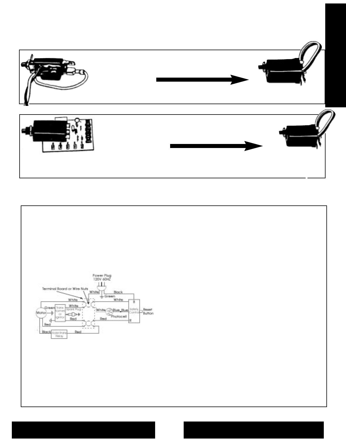
- Desa Common Safety Controls 13
- Part No. M50398 15
- Toro Service Information 16
- Toro Service Info 17
- Enerco Service Information 20
- Enerco Service Info 20
- L.B. White Service Info 21
- Troubleshooting 21
- Common Parts 22
- Pre-Packaged Kits/Parts 23 22
- Common Replacement Parts 22
- REPLACEMENT PARTS INDEX 22
- Pre-Packaged Parts 23
- Enerco Oil Fired Heaters 24
- 2003-2004 Model Year 25
- Enerco Oil 75-175,000 BTU 26
- 2003 - 2004 Model Year 26
- Enerco Oil 50-175,000 BTU 28
- 2004-2005 Model Year 28
- Enerco Oil 50-210,000 BTU 30
- 2005 - 2006 Model Year 30
- 2006 - 2007 Model Year 32
- 2007 - 2008 Model Year 34
- 2008 - 2009 Model Year 36
- 2009-2010 Model Year 40
- L.B. White Oil Fired Heaters 42
- L.B. White Oil 70,000 BTU 43
- L.B. White Oil 165,000 BTU 44
- L.B. White Oil 45-75,000 BTU 45
- L.B. White Oil 125-170,000 46
- L.B. White Oil 210,000 BTU 47
- L.B. White Oil Quick Parts 48
- Desa Oil Fired Heaters 49
- Desa 35-70,000 BTU HSI 50
- Desa 40-70,000 BTU HSI 52
- Desa 40,000 BTU HSI 54
- Desa 50-70,000 BTU HSI 55
- 110-165,000 BTU Forced Air H 56
- .S.I. Desa Oil Fired Heater 56
- Desa 110-165,000 BTU HSI 58
- Desa 110-155,000 BTU HSI 62
- Desa 200,000 BTU HSI 64
- 200,000 BTU Forced Air H 64
- .I. Desa Oil Fired Heater 64
- Desa Pro Plus Series 68
- Desa Pro Plus Series Heaters 68
- Desa Burners & Wheel Kit 70
- Oil Fired 71
- Service Manual 71
- Gas Fired Service 71
- Desa Oil 35-50,000 BTU 72
- Desa Oil 70,000 BTU 74
- Desa Oil 100-165,000 BTU 76
- Desa Oil 100-200,000 BTU 78
- Desa Oil 200,000 BTU 80
- Desa Oil 350,000 BTU 82
- Desa 350 & 600,000 BTU 83
- Desa Oil 600,000 BTU 84
- Desa Oil Quick Parts Ref 85
- Metal 108088-19 90
- Plastic 113279-01 90
- Metal 108088-16 90
- Metal 108088-11 91
- Plastic 113279-02 91
- Metal 108088-10 92
- Plastic113279-03 92
- Metal108088-17 92
- Plastic113279-04 92
- Scheu Oil Fired Heaters 98
- Scheu Oil 50-150,000 BTU 99
- Scheu Oil 100-150,000 BTU 100
- Scheu Oil 75-175,000 BTU 101
- Scheu Oil Quick Parts Ref 102
- HEATER INDEX 103
- Toro Portable Heaters 103
- Toro Oil 40-55,000 BTU 104
- Toro Oil 60-150,000 BTU 105
- Toro Oil 40-150,000 BTU 106
- Key Part BTU SIZES 108
- (Old Style) 108
- Toro Motor Assembly 108
- Toro Filter Assembly 110
- Order Parts 111
- Toro Oil 120-230,000 BTU 112
- Toro Oil 155-230,000 BTU 114
- Toro 155-230,000 Burner 116
- Pro Temp Oil Heaters 117
- 45-215,000 Kerosene 118-119 117
- Pro Temp Oil Fired Heaters 117
- Pro Temp 45-215,000 BTU 118
- Gas Heater Service Info 120
- Gas Fired Heaters 121
- Propane Tanks 128
- Propane Hoses 128
- Propane Supplies 129
- Propane Quick Disconnects 130
- Enerco Gas Fired Heaters 131
- Enerco LP 9,000 BTU 132
- Enerco LP 12-35,000 BTU 134
- Enerco LP 24,000 BTU 135
- “Big Buddy” 135
- Key Part 135
- No. No. Description 135
- Enerco LP 24-42,000 BTU 136
- Enerco LP 35,000 BTU 137
- Enerco LP 45-75,000 BTU 138
- Enerco LP 55,000 BTU 139
- Enerco LP 55-125,000 BTU 140
- Enerco LP 80,000 BTU 142
- Enerco LP 85,000 BTU 143
- Enerco LP 200,000 BTU 145
- Enerco LP/NG 125,000 BTU 146
- 2009 - 2010 Model Year 147
- Enerco LP 125,000 BTU 148
- Enerco LP 170,000 BTU 149
- Enerco LP 400,000 BTU 153
- Enerco Gas Quick Parts Ref 154
- L.B. White Gas Heaters 156
- L.B. White 225,000 BTU 157
- L.B. White LP 225,000 BTU 158
- L.B. White LP 100,000 BTU 159
- No. Description Number 159
- L.B. White LP 250,000 BTU 160
- L.B. White LP 155,000 BTU 162
- Key Part Number 163
- No. Description 155 155ULTRA 163
- L.B. White LP 400,000 BTU 164
- No. Description 400 400ULTRA 165
- L.B. White 80,000 BTU 166
- L.B. White 170,000 BTU 167
- L.B. White 170,000 BTU 170
- L.B. White 350,000 BTU 171
- L.B. White 350,000 BTU 172
- L.B. White Quick Parts 174
- Desa Gas Fired Heaters 180
- Desa LP 25,000 BTU 181
- Desa LP 30,000 BTU 182
- No. Number Description 182
- Desa LP 35-50,000 BTU 183
- Desa LP 50,000 BTU 184
- Desa LP 55,000 BTU 186
- Desa LP 85,000 BTU 188
- Desa LP 80,000 BTU 190
- Desa LP 100,000 BTU 191
- Desa LP 125,000 BTU 192
- Desa LP 170,000 BTU 193
- Desa NG 150,000 BTU 194
- Desa LP 150,000 BTU 195
- Desa LP 200,000 BTU 197
- Desa NG 250,000 BTU 198
- Desa LP 375,000 BTU 199
- Desa Gas Quick Parts Ref 200
- Patio Comfort Heater 208
- Scheu Gas Fired Heaters 209
- Scheu Gas Fired 209
- Scheu LP 30,000 BTU 210
- Scheu LP 35,000 BTU 211
- Scheu LP 40,000 BTU 212
- Scheu Heater 214
- Scheu LP 80,000 BTU 215
- Scheu LP 50-80,000 BTU 216
- Scheu LP 150,000 BTU 217
- Key No. Part No. Description 219
- Scheu LP 170,000 BTU 220
- Scheu LP 200,000 BTU 221
- Scheu LP 350,000 BTU 223
- Scheu LP 175-350,000 BTU 224
- Scheu NG 80-150,000 BTU 226
- (qty. 3) 226
- * Not shown on exploded view 226
- Universal Wiring Diagrams 227
- Model 150FAS w/Fenwall 229
- Scheu Wiring Diagrams 229
- Model 3500FAS 231
- Model SPC170T/170FAST 231
- Model 3500FACV 232
- Model 3500FACNG 232
- Model 3500FA/3500FANG 232
- Scheu Gas Quick Parts Ref 233
- Pro Temp Gas Fired Heaters 239
- Pro Temp Gas Heaters 239
- Pro Temp Propane Heaters 240
- No. Description 240
- Pro Temp LP 40-150,000 BTU 240
- Pro Temp Wiring 241
- Space Ray Heaters 242
- Space Ray 100-212,000 BTU 243
- Space Ray 250,000 BTU 244
- Heat Wagon/SureFlame Heaters 245
- Heat Wagon 90,000 BTU 246
- Heat Wagon 110,000 BTU 247
- Heat Wagon 180,000 BTU 248
- Heat Wagon 210-310,000 BTU 249
- Heat Wagon 300,000 BTU 250
- Sure Flame 400,000 BTU 251
- Sure Flame 1,500,000 BTU 252
- MISCELLANEOUS INDEX 253
- Standard Nylon Cable Ties 254
- Nozzles 255
- Heater Service Equipment 256
- Wick Heater Accessories 257
- ACCESORIES INDEX 257
- Batteries 258
- Wick Selection Chart 259
- Wick Heater Chimney Glass 262
- NEED PHP CREDIT 263
- NO COMPUTER 263
- Fax Toll Free: 800-255-7985 265
- Why Choose 268
© 2020, manymanuals.com. All rights reserved. | 1.028 s |
 Manymanuals.com
 Manymanuals.de
 Manymanuals.fr
 Manymanuals.it
 Manymanuals.pl
 Manymanuals.cz
 Manymanuals.es
 Manymanuals-pt.com
Comments to this Manuals