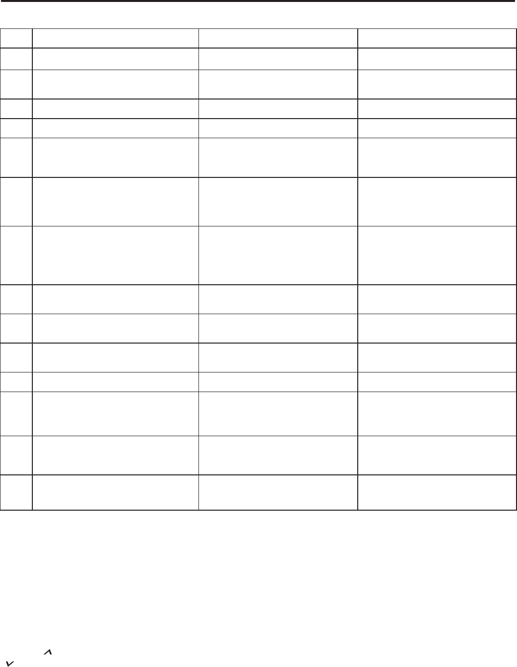
Electronic Control Error Code Diagnostics
Error
Code
esuaC elbissoPtinU yB nekaT noitcAnoitalsnarT edoC
yllamroN gnitarepO tinUenoNeerF rorrEFE
02
An extreme low voltage condition exists <198V
for 230V units and <239V for 265V units.
Shut unit down. Flash error code. When
voltage rises to adequate level normal unit
operation is restored.
• Inadequate power supply
• Defective breaker
• Blown fuse
03
Return air thermistor sensor open or
short circuit
Leave unit running. Alternately flash error
code and set point.
• Defective sensor
04
Indoor coil thermistor sensor open or
short circuit
Leave unit running. Alternately flash
error code and set point.
• Defective sensor
05
Outdoor coil thermistor sensor open
or short circuit
Leave unit running. Switch to Electric Heat
Mode (Heat Pump only). Alternately flash
error code and set point.
• Defective sensor
06
Outdoor coil Temperature > 175° F for
2 consecutive minutes. (Heat Pump
models only)
Shut unit down for 5 minutes, Alternately
flash error code and set point, then try again
2 times, if unit fails the 3rd time then shut
unit down and alternately flash error code
and set point.
• Dirty coil
• Fan motor failure
• Restricted air flow
• Non-condensables in refrigeration sys
07
Indoor coil temperature <30° F for 2
consecutive minutes.
Shut down Compressor, and continue fan
operation. Alternately flash error code and
set point until the indoor coil thermistor
reaches 45° F. Then, (after lockout time of
180 to 240 seconds expires), re-energize
the compressor .
• Dirty filters
• Dirty coil
• Fan motor failure
• Restricted air flow
• Improper refrigerant charge
• Restriction in refrigerant circuit
08
Unit cycles (Heat or Cool demand) >
9 times per hour
Leave unit running. Store error code in
memory.
• Unit oversized
• Low load conditions
09
Unit cycles (Heat or Cool demand) <
3 times per hour
Leave unit running. Store Error Code in
memory.
• Unit undersized
• High load conditions
10 Room Freeze Protection triggered
Leave unit running. Alternately flash error
F°04 woleb llef erutarepmet mooR •.tniop tes dna edoc
11 No Signal to “GL or “GH” terminal Shut unit down. Flash error code.
• Defective remote thermostat
• Defective thermostat wiring
12 Discharge air temperature >185° F
Shut down Compressor and/or Heater, and
energize high fan. Alternately flash error
code and set point. If condition repeats
three times in one hour, shut unit down.
• Restricted air flow
• Fan motor failure
13
Pressure switch jumper wire loose/missing
High Pressure switch open (If so equipped)
Shut unit down. Flash error code.
• Dirty coil
• Fan motor failure
• Restricted air flow
• Non-condensables in refrigeration system
14
Discharge air temperature sensor open or
shorted
Leave unit running. Alternately flash error
code and set point.
• Defective Sensor
16
Diagnostics
The Friedrich Smart Center continuously monitors
the PTAC unit operation and will store service codes if
certain conditions are witnessed. In some cases the unit
may take action and shut the unit off until conditions are
corrected.
To access the error code menu press the ‘Heat’ and
‘High Fan’ buttons simultaneously for three seconds. If
error codes are present they will be displayed. If multiple
codes exist you can toggle between messages using
the temp button. To clear all codes press the temp
button for three seconds while in the error code mode.
To exit without changing codes press the ‘Low Fan’ button.
EF = Error Free
Test Mode
For service and diagnostic use only, the built-in
timers and delays on the PTAC may be bypassed
by pressing the ‘Cool’ and ‘Low Fan’ buttons
simultaneously for three seconds while in any
mode to enter the test mode. CE will be displayed
when entering test mode, and OE will be displayed
when exiting. The test mode will automatically be
exited 30 minutes after entering it or by pressing
the ‘Cool’ and ‘Low Fan’ buttons simultaneously
for three seconds.
Note:
To access the Test Mode while under remote wall
thermostat operation, remove thermostat’s wires
at the terminal block on the electronic control
board then connect a jumper wire between GL
and GH.
 Manymanuals.com
 Manymanuals.de
 Manymanuals.fr
 Manymanuals.it
 Manymanuals.pl
 Manymanuals.cz
 Manymanuals.es
 Manymanuals-pt.com
Comments to this Manuals