REMOTE THERMOSTAT AND LOW VOLTAGE
CONTROL CONNECTIONS
Room Thermostats
Room thermostats are available from several different
manufacturers in a wide variety of styles. They range from
the very simple Bimetallic type to the complex electronic set-
back type. In all cases, no matter how simple or complex,
they are simply a switch (or series of switches) designed to
turn equipment (or components) “ON” or “OFF” at the desired
conditions.
An improperly operating, or poorly located room thermostat
can be the source of perceived equipment problems. A careful
check of the thermostat and wiring must be made then to
insure that it is not the source of problems.
Remote Thermostat
All Friedrich PD model PTAC units are factory congured to
be controlled by either the chassis mounted Smart Center
or a 24V single stage remote wall mounted thermostat. The
thermostat may be auto or manual changeover as long as the
control conguration matches that of the PTAC unit.
For Heat Pump equipped units: A single stage, heat/cool
thermostat with a terminal for a reversing valve operation is
required. Terminal “B” should be continuously energized in the
heat mode and terminal “G” should be energized whenever
there is a call for heating or cooling. Typically, a single stage,
heat/cool thermostat designed for use with electric heat
systems will meet the above requirements.
To control the unit with a wall mounted thermostat follow
the steps below:
1) With the front cover removed locate the low voltage
terminal strip at the lower portion of the Smart Center.
2) Remove the jumper between the ‘GL’ and GH’
terminals.
3) The control is now congured for control by a wall
thermostat. The Smart Center will no longer control the
unit.
4) If desired the accessory escutcheon kit (PDXRT) is to
be used, install it over the existing control panel
Note: To revert back to the Smart Center control of the unit
replace the jumper wire between the ‘GL’ and ‘GH’ terminals
that was removed in step 1.
Remote Thermostat Control
Heat Pump with Electric Heat Operation
When there is a call for heat from the wall thermostat the
control board will receive signals on terminals W, B, GL or
GH. During compressor lock-out time, the electric heat will
turn on rst. When the compressor lock-out time is up, the
compressor will turn on. If the outdoor coil temperature sensor
drops to 30° F or less for 2 consecutive minutes then the unit
will switch to electric heat.
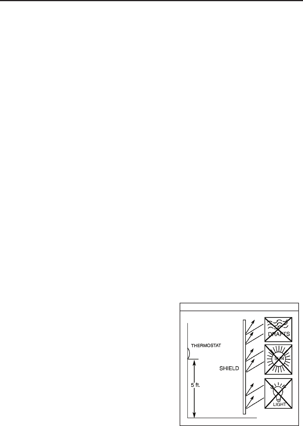
Location
The thermostat should not be mounted where it may be
affected by drafts, discharge air from registers (hot or
cold), or heat radiated from the sun or appliances.
The thermostat should be located about 5 Ft. above the
oor in an area of average temperature, with good air
circulation. Close proximity to the return air grille is the
best choice.
Mercury bulb type thermostats MUST be level to control
temperature accurately to the desired set-point. Electronic
digital type thermostats SHOULD be level for aesthetics.
Thermostat Connections
C = Common Ground
W = Call for Heating
Y = Call for Cooling
R = 24V Power from Unit
GL = Call for Low Fan
GH = Call for High Fan
B = Reversing Valve Energized in heating mode
(PDH Models Only)
*If only one G terminal is present on thermostat connect to
GL for low fan or to GH for high fan operation.
NOTE: It is the installer’s responsibility to ensure that all
control wiring connectiions are made in accordance with
the Friedrich installation instructions. Improper connection
of the thermostat control wiring and/or tampering with the
unit’s internal wiring can void the equipment warranty.
Questions concerning proper connections to the unit
should be directed to the factory: 210-357-4400.
Thereafter, the unit will switch back to heat pump heat if the
outdoor coil temperature sensor rises to 45’ F or greater.
Thermostat Location
Manual Changeover Thermostat
10
 Manymanuals.com
 Manymanuals.de
 Manymanuals.fr
 Manymanuals.it
 Manymanuals.pl
 Manymanuals.cz
 Manymanuals.es
 Manymanuals-pt.com
Comments to this Manuals