Remington BS1812A User Manual Page 8
- Page / 48
- Table of contents
- BOOKMARKS
- 18VOLT CORDLESS TRIMMER/EDGER 1
- SAVE THESE INSTRUCTIONS 2
- WARNING 4
- PRODUCT IDENTIFICATION 5
- SPECIFICATIONS 5
- WARNING 6
- Safety Instructions 7
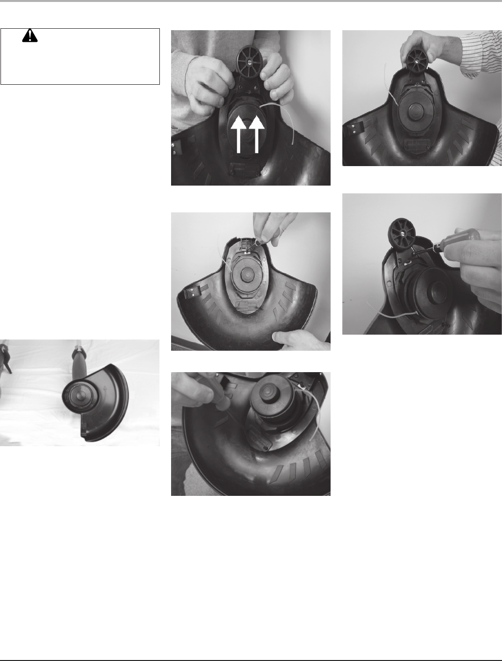
- TRIMMER ASSEMBLY 9
- WARNING: 10
- CAUTION: 12
- TRIMMER/EDGER OPERATION 13
- SAVE THESE 15
- INSTRUCTIONS 15
- WARRANTY INFORMATION 16
- DE 18 VOLTIOS 17
- GUARDE ESTAS INSTRUCCIONES 18
- ADVERTENCIA 19
- NOTAS IMPORTANTES DE 22
- CARGA DE BATERÍA 22
- SUJECIÓN DEL ASA FRONTAL 24
- REGULABLE 24
- ADVERTENCIA 27
- PRECAUCIÓN 27
- USO COMO RECORTABORDES 28
- INFORMACIÓN DE GARANTÍA 31
- GUIDE DU PROPRIÉTAIRE 32
- CONSERVEZ CES DIRECTIVES 33
- MISE EN GARDE 34
- CONSERVEZ 34
- CES DIRECTIVES 34
- FRANÇAIS 37
- PILE RECHARGEABLE 37
- INFORMATION SUR LA GARANTIE 46
- 122042-01 48
Related products and manuals for Gardening equipment Remington BS1812A


 (64 pages)
© 2020, manymanuals.com. All rights reserved. | 1.168 s |
 Manymanuals.com
 Manymanuals.de
 Manymanuals.fr
 Manymanuals.it
 Manymanuals.pl
 Manymanuals.cz
 Manymanuals.es
 Manymanuals-pt.com
Comments to this Manuals